Below you see the obvious dip in the track in the area of the entrance switch into my layout area of East Shumala. This was discovered by the usual method, derailments during an operating session (for a description of the session, not the problem, see: https://modelingthesp.blogspot.com/2023/12/december-operating-session.html ). I amused some of the visiting operators, when this dip was discovered, by exclaiming “It’s a new dip!” But I was correct; this wasn’t evident six months ago.
But in fact the problem is not only at this location. Moving to the right of the above photo, it was evident that though the main line through Shumala is level, the switch diverging toward East Shumala from the main line is downhill over a longer area that suggested in the photo above. So a wider area needed to be corrected.
I have a way of correcting dips, as I showed in the previous post (link in the first paragraph at the top of this post). I force a putty knife into the track support (installed too long ago to be sure, but I suspect Homasote) under the area that needs to be raised. This is near but not the same place as the area I corrected in that previous post (top of post).
With an opening created, I slide in some pieces of Evergreen styrene strip, 0.040 x 0.125 inches (HO scale 4 x 12), about an inch long, into the opening where the putty knife was.
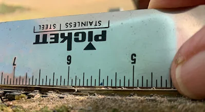
As you see above, these were a little too long, and the protruding ends were cut off. Then a check with my steel ruler showed that there was no longer a dip in the track. In the photo below, the rail joint is at the 10-3/4-inch mark on the ruler, and there is no discernible dip any longer. And the mainline track is also raised to be level, correcting what is shown in the second photo from the top of this post.
The very ends of the styrene strips are evident above, but these will be
covered with ballast in my upcoming tour of the layout to correct
innumerable areas where scenic ground cover needs to be added or
renewed.
With this track corrections, repeated switching moves revealed no derailments (of course, as every layout owner knows, bringing in guests may reveal a different result). I realize that this and other track subsidence problems probably indicate that my sub-roadbed or track boards may have shrunk, warped or shifted in some way, but rather than tear up the layout down to the framing to fix things from the bottom up, I will continue to make these kinds of “corrections” to the track.
Tony Thompson


0 Comment